Installing
Download AlterMesh
If you haven’t done so already, download AlterMesh from the Unreal Marketplace.
Activation
After downloading, locate the plugin in the plugin tabs within Unreal Engine. Activate it to enable its functionalities.
Configure Blender Executable
Getting Started
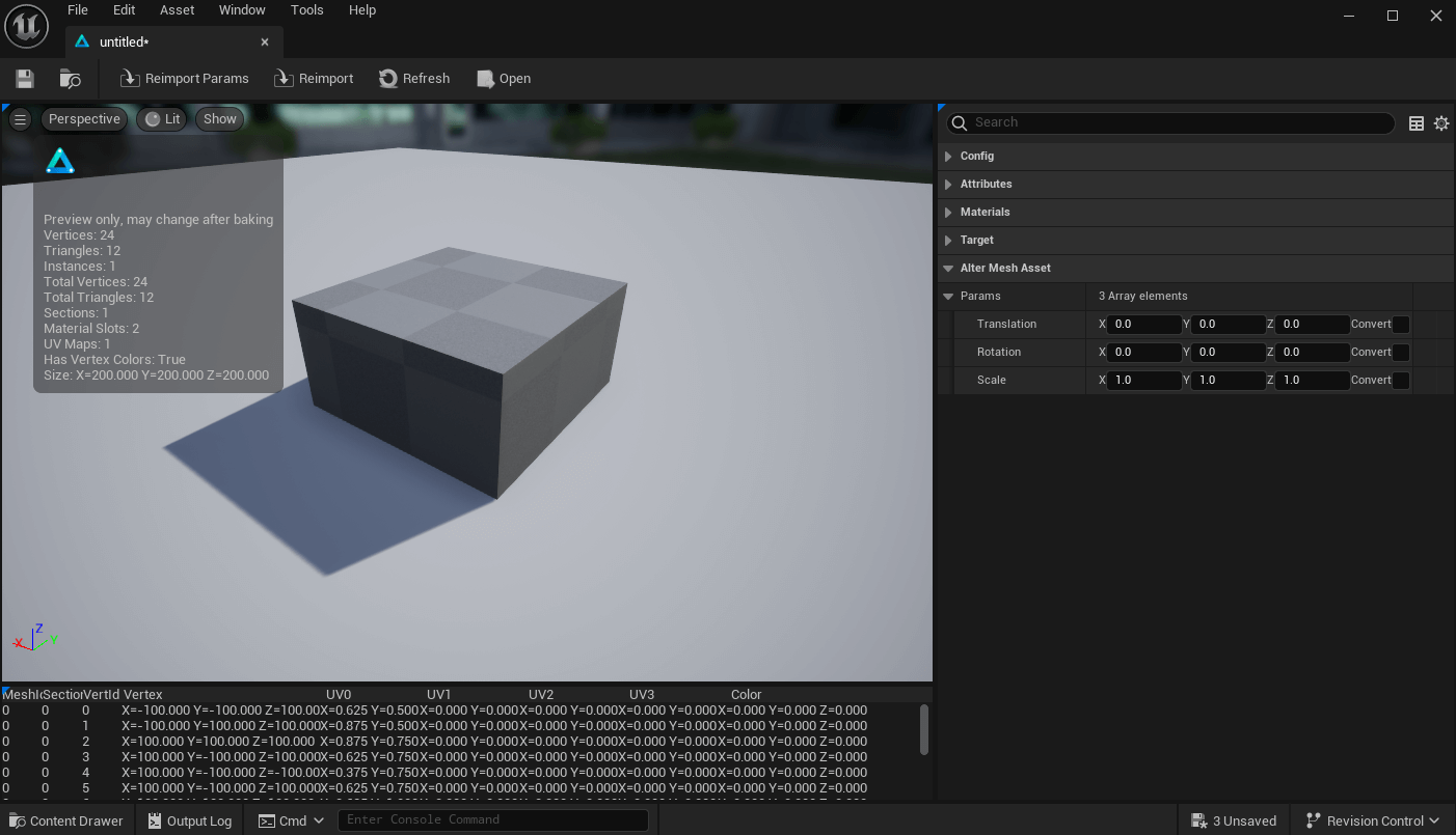
With AlterMesh successfully installed and configured, you can now start using its features. Explore bundled examples by clicking the content button on the toolbar or read below how to create your first tool
Your First tool
- Open Blender
- Add a geometry nodes to the default cube
- Add a transform node
- Connect the inputs to the Group Input
- Save and Close
- Drag the saved file to the UnrealEngine content browser
- Drag the asset into the viewport
Asset Editor
File Configuration
Filename and Object name will be filled automatically upon importing a .blend file, and can be left as is.
The collision parameter lets you choose a parameter to toggle during the collision creation, allowing to import custom collision created by your GeometryNodes.
By default, assets will be converted to Static Meshes, you can change this behavior in the Converter Class setting.

Attributes

Materials
During the import process, AlterMesh will look in your blend files and list all of the materials available in your .blend, this will allow you to map used or unused materials with an Unreal equivalent.
Unfortunately AlterMesh will not import your materials automatically, this would require a translation of Blender-Unreal materials which is not simple. Please remake the material in Unreal or assign a different one.

Parameters
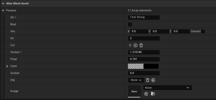
Node panels, parameter tooltips, Min/Max values are supported
Exposing Parameters
Input Group
Only parameters that are connected to the Group Input are available. If you add more parameters to the group input, you can click on the Reimport Parameters button on the toolbar of the asset editor to refresh the parameter list.
Param settings
Node panels, parameter tooltips, Min/Max values are supported.
You must assign unique names to Node panels, otherwise they will be combined into a single panel.
Vector Param
This is disabled by default, and can be turned on when you need that the Front/Right of unreal is the same as the Front/Right of blender, generally for “Position” or “Direction” kind of parameters.
Geometry Params
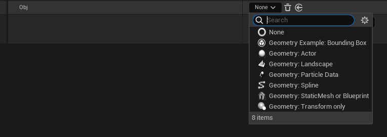
When you expose a pin of this type, in Unreal you will be able to select which kind of geometry you want to export, for example a Spline or a Static Mesh asset.
Geometry Parameters
Overview
Static Mesh asset or Blueprint

Transform Only
Equivalent to the “Empty” object in blender, it will only export transform information to your node setup, generally used as a pivot or as a target.
Draw As: how you want to visualize the transform, such as a cube or a single point.

Actor
Use this input if you need the location of the actor to be available to your geometry nodes setup.

Landscape
Spline
Creates a spline curve to be edited in Unreal. Exposed params with a curve in its modifier defaults will be defaulted to this geometry type.
Resolution: How many points per segment the curve will have in Blender.

Collection

Expanding Geometry Types
Your project may create new geometry types (C++) if you need extra functionality.
					// .h

// Example Geometry type that exports the bounding box of the selected actor
// Must be paired with a file in ThirdParty/Extensions folder
UCLASS(meta=(DisplayName="Geometry Example: Bounding Box"))
class ALTERMESHEXAMPLESEDITOR_API UAlterMeshExamplesGeometryBoundingBox : public UAlterMeshGeometryBase
{
	GENERATED_BODY()
public:

	UPROPERTY(EditAnywhere, BlueprintReadWrite)
	AActor* Actor;

	virtual bool ShouldExport() override { return !!Actor; }
	virtual void Export(FAlterMeshExport& Exporter) override;
};


// .cpp
void UAlterMeshExamplesGeometryBoundingBox::Export(FAlterMeshExport& Exporter)
{
	Super::Export(Exporter);

	FVector Origin, Extent;
	Actor->GetActorBounds(false, Origin, Extent);
	FBox Bounds = FBox::BuildAABB(FVector::ZeroVector, Extent);

	// Create a cube from bounds
	TArray<fvector> Vertices;
	TArray<int32> Indices;
	UAlterMeshExamplesLibrary::MakeCube(Bounds, Vertices, Indices);

	// Convert scene
	for (FVector& Vertex : Vertices)
	{
		Vertex = Exporter.ToBlenderMatrix.TransformPosition(Vertex);
	}

	Exporter.WriteArray(Vertices);
	Exporter.WriteArray(Indices);
}
</int32></fvector>
The exporting code must be paired with a python file with the same name in the AlterMesh/Source/ThirdParty/ folder that will be used to import your geometry in Blender:
					import bpy
from library import Reader
import numpy as np

def import_obj(object_name):
    locations = Reader(np.float32).as_list(3)
    indices = Reader(np.int32).as_array(3)

    #create a mesh
    mesh = bpy.data.meshes.new("NewMesh")
    obj = bpy.data.objects.new(mesh.name, mesh)

    mesh.from_pydata(locations, [], indices)

    return obj

def used_for_object(obj):
    False

def get_defaults(obj):
    pass
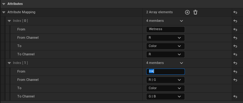
Attribute Mapping
Supported Output Types
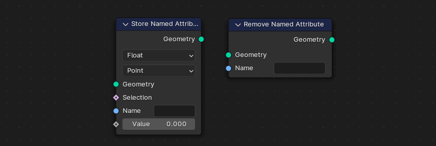
In the picture below, the float attribute is named “MyOutput1”

Attribute by name
Mapping
To Channel: Which channel to save the attribute to.
Runtime Cinematics
Runtime
When should I use runtime?
- Cinematics
- Virtual Presentations
- Music visualization
- Experimental projects
- Visual Effects
When should I NOT use runtime?
- Games that will be ported to consoles
- When VAT/ALEMBIC are better alternatives
- When performance is a concern
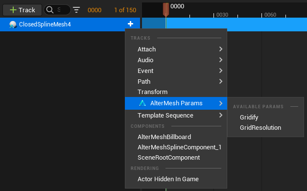
Keyframing
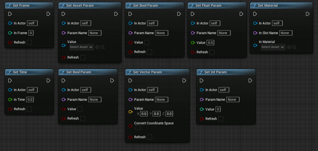
Blueprints
Performance
The simulation is done by Blender and can only be as fast as the Geometry Node Tree.
Use the timings in Blender to profile how long each frame will take. AlterMesh will add from 10% to 50% on top of the node Tree, heavily depending on the number of triangles that have to be exported.

Troubleshooting
Nothing shows up
- Make sure you set up your executable path in Project settings -> AlterMesh -> Executable path
- Make sure the .blend files, Unreal, and the Blender executable are in the same driver, altermesh uses relative paths for source control purposes, and it may not find your files if its not in the same drive
- Check if the .blend file you are trying to import and the executable path are the same blender version.
- Check the output log for any Unreal errors
- Check the output log after using the command altermesh.debugprocessoutput 1
- Try using altermesh.debuginteractive 1 to enable launching a visible (but not interactable) blender instance and see if it is indeed opening
Curves cannot be edited
Objects are not instancing
Plugin “AlterMesh” failed to load because module “AlterMesh” could not be loaded
Open the folder AlterMesh/Source/Extern/ and copy the AlterMesh.dll file to AlterMesh/Binaries/Win64/ folder
This should be fixed in 2.3 and above.
Converters
Converter Types
Convert to Static Mesh
Convert to Foliage
Convert to Vertex Animation Textures (VAT)
Do not convert
Creating new converters
					UCLASS(BlueprintType, Blueprintable, meta=(DisplayName="Converter Example:
Convert to Bounding box"))
class UAlterMeshExamplesConverterBoundingBox : public
UAlterMeshConverterBase
{
GENERATED_BODY()
public:
UAlterMeshExamplesConverterBoundingBox();
// Properties added here will be prompted for user input
UPROPERTY(EditAnywhere)
UMaterialInterface* Material;
virtual void Convert(AAlterMeshActor* InActor) override;
};
					void UAlterMeshExamplesConverterBoundingBox::Convert(AAlterMeshActor*
InActor)
{
// If you inherited from UAlterMeshConverterStaticMesh call this to create
the StaticMesh assets
// Super::Convert(InActor);
// And this would contain your newly created meshes, or the replacement
meshes/blueprints
// ConverterSteps[i].AssetToUse
FBox Bounds;
// Find the bounds of all meshes and all instances
ForEachSection(InActor, [&](FAlterMeshSection& Section)
{
FBox MeshBounds = FBox(Section.Vertices);
for (FMatrix InstanceMatrix : Section.Instances)
{
Bounds += MeshBounds.TransformBy(InstanceMatrix);
}
});
FActorSpawnParameters SpawnInfo;
SpawnInfo.OverrideLevel = InActor->GetLevel();
SpawnInfo.SpawnCollisionHandlingOverride =
ESpawnActorCollisionHandlingMethod::AlwaysSpawn;
SpawnInfo.bNoFail = true;
// Proc mesh to display bounds
AActor* NewActor = InActor->GetWorld()->SpawnActor<aactor>(SpawnInfo);
UProceduralMeshComponent* ProcMesh =
NewObject<uproceduralmeshcomponent>(NewActor);
NewActor->SetRootComponent(ProcMesh);
NewActor->AddInstanceComponent(ProcMesh);
ProcMesh->RegisterComponent();
NewActor->SetActorTransform(InActor->GetActorTransform());
if (Material)
{
ProcMesh->SetMaterial(0, Material);
}
// Create a cube from bounds
TArray<fvector> Vertices;
TArray<int32> Indices;
UAlterMeshExamplesLibrary::MakeCubeFromBox(Bounds, Vertices, Indices);
TArray<fvector> Normals;
TArray<fvector2d> UVs;
TArray<fcolor> Colors;
TArray<fprocmeshtangent> Tangents;
ProcMesh->CreateMeshSection(0, Vertices, Indices, Normals, UVs, Colors,
Tangents, false);
}</fprocmeshtangent></fcolor></fvector2d></fvector></int32></fvector></uproceduralmeshcomponent></aactor>


